Interfacing with host hardware
RISC OS Pyromaniac is intended to be used to debug and test interfaces and allow experimenting with other ways of working, using regular RISC OS interfaces. Most of the interfaces that we have in the system can be configured to act in certain ways. For example, the OS_Memory interfaces don't actually configure the memory that we use, but instead return some values that look plausible, and that you can change. That way you can vary what the system returns to see how your program reacts.
Some of the interfaces, though, can talk to the host system. In the UI, that means things like the mouse and the keyboard but also interfaces like the Portable module allow you to find out the state of the host system. This sort of interface is useful for manually testing how your program works when it's run with live data - but it also makes the system more like a real machine, and you can learn even more about how your program should work. Plus if it doesn't work, you have much more diagnostic information available than you ever would with RISC OS Classic.
One small, interesting, thing that came up when creating the Portable module was that the RISC OS interfaces for reporting the battery state had no way of saying that the battery had failed or should be serviced. This isn't too surprising as the management system is based on Acorn's A4 hardware which had a far simpler battery management unit than is present in most modern systems. My laptop does indeed report that its battery needs replacing, and this is fed through to the interfaces for the Portable module.
These Portable changes happened last year, and it seemed like there should be more interfaces to the host hardware. The important thing, though, is that interfaces to the host hardware in RISC OS Pyromaniac are only through standard RISC OS interfaces. RISC OS Pyromaniac does not provide any controller chip access, memory-mapped registers, or DMA transfers. What it does offer are the RISC OS interfaces that you can call.
IIC interfacing through MCP2221
The IIC module was one of the first modules implemented, created just over a month after the Pyromaniac project started. The original implementation could be extended through registered addresses that would dispatch to the code that implemented the device. The only device that was implemented this way was the PCF8583 - the RTC/NVRAM chip used in the Risc PC. The IIC module would look at the registered devices and dispatch the request to the handler for the address supplied. This meant that the RTC and the NVRAM could be accessed easily by users of the system through the defined API.
In RISC OS Select, the RTCHW module and the NVRAMHW module used the I²C interface to access the chip, so by implementing these interfaces, those classic modules would work. I wanted to be able to talk to some real devices, though. IIC is one of the simpler hardware interfaces and it isn't difficult to integrate a host API into RISC OS Pyromaniac. So I ordered a USB-based I²C debug board, and an I²C device that I might talk to - a little LCD display.
The debug board is based on the MCP2221, which is a nice chip that has I²C, GPIO, ADC and DAC functions, and there are Python libraries to use it. But before I could actually use the device to talk to I²C, I needed to move around the code that was already there. Rather than being hardcoded, the IIC module needed to be able to use multiple implementations so that we can configure it to use either the internal devices or this real hardware device.
Fortunately, moving the code around so that we can use multiple implementations is now very easy. Not only am I quite used to doing that, but there are a lot of examples I have already written which I can use as a reference. Originally the IIC implementation for the MCP2221 was just some simple calls to the pymcp2221a Python library. However, as time went on, I found it to be pretty bad at handling errors, and when things went wrong it didn't work well. Over time a lot of patches have been made to the module to make it more reliable within RISC OS Pyromaniac.
The LCD device I picked was just one that looked interesting and which had some documentation to help with understanding how to talk to it. It is basically a combination of two different I²C devices - one for the RGB backlight and one for the LCD controller. That means that not only do I get to talk to a device, but I have to be able to talk to multiple devices to make this display properly.
Getting the MCP2221 to talk to the I²C initially wasn't hard, and the operations that it could perform were write-only as for this LCD device I did not need any read operations. Later work made the read operations work just as well, too. The result is that from a small BASIC program, you can write text onto the LCD display.
REM>LCD
REM Turn on and show a message on the LCD module (LCD1602)
REM https://thepihut.com/products/rgb-16x2-i2c-lcd-display-3-3v-5v

DIM data% 16

data%?0 = &80:data%?1 = &28:SYS "IIC_Control", &7c, data%, 2
data%?0 = &80:data%?1 = &28:SYS "IIC_Control", &7c, data%, 2
data%?0 = &80:data%?1 = &c:SYS "IIC_Control", &7c, data%, 2
data%?0 = &80:data%?1 = &1:SYS "IIC_Control", &7c, data%, 2
data%?0 = &80:data%?1 = &6:SYS "IIC_Control", &7c, data%, 2
data%?0 = &0:data%?1 = &0:SYS "IIC_Control", &c0, data%, 2
data%?0 = &8:data%?1 = &ff:SYS "IIC_Control", &c0, data%, 2
data%?0 = &1:data%?1 = &20:SYS "IIC_Control", &c0, data%, 2
data%?0 = &4:data%?1 = &ff:SYS "IIC_Control", &c0, data%, 2:REM Red
data%?0 = &3:data%?1 = &40:SYS "IIC_Control", &c0, data%, 2:REM Green
data%?0 = &2:data%?1 = &FF:SYS "IIC_Control", &c0, data%, 2:REM Blue

REM Print a message
a$ = "Hello world"
data%?0 = &80:data%?1 = &80 + 0:SYS "IIC_Control", &7c, data%, 2:REM x=0, y=0
FOR I = 1 TO LEN(a$)
    data%?0 = &40:data%?1 = ASC(MID$(a$, I, 1)):SYS "IIC_Control", &7c, data%, 2
NEXT
One thing that I tried to do with each of the programs that I created was to put the example code that I wrote up on my riscos-examples GitHub repository. There's a more advanced and annotated version of the above program on there.
I bought a small I²C LED matrix, as it had a different controller and therefore was something else fun to work with. This device was pretty interesting to work with but I kept getting the device turning itself off when I looked at it sharply. This turned out to be a problem with having multiple devices on the I²C bus if you've not wired them up properly. It was another reminder that hardware isn't something I'm especially fond of. As with the LCD display, the code was put up on the examples site.
With a couple of simple devices working, it might be nice to be able to do something a bit more impressive.
GPIO through MCP2221
Once I got the IIC module working with the MCP2221, I tried creating a GPIO module so that I could access some of the pins on the device. I had ordered a Blinkt RGB lights device. This is a device that is intended to work with the Raspberry Pi and has its pins all lined up so that you just plug it into the Pi's header. Obviously, I'm not doing that as I'm not using a Pi, but GPIO pins are pretty standard, and there are nice pin-out diagrams that show how it needs to be connected up.
The GPIO module on RISC OS isn't very nice to work with. The SWI calls are basically an extension of the GPIO operations on a very old board, which doesn't map to all the devices, and there's really no easy way of expanding with other boards. An attempt has been made in the later versions of the module to push the interface to work better, but it still isn't a plug-and-play design. Much of the interface cannot work with other systems and you cannot detect features well.
That said, the basic functionality isn't too bad, and creating an implementation of the module wasn't so hard. From the start, the Pyromaniac GPIO module was designed to use different implementations so that it can drive either real hardware or return dummy values. As more functionality was added, there were a few more features that became available, like the definition of how the lines are driven. The first driver was the MCP2221, and the first device I could drive was the Blinkt RGB display.
Again, the code used to drive it is available so that people can see how you work with GPIO on RISC OS.
Driving some lights is fun, but I'd also picked up some 7-segment displays which seemed like they might be fun to control. Each of the segments is individually programmable so you don't have to make it just show numbers. This was kinda fun to do, as it uses a quite different protocol to clock bits into the device. The mechanism for doing this was (like many of these hardware examples) taken from Python example code, so it wasn't too hard to reproduce. In most of the cases, I had the datasheet to refer to so that I can understand what was actually being done.
Writing words is a bit harder with just 4 7-segment characters, but you can see a stylised 'Hello from Pyro' flash up. The code to drive this is again available.
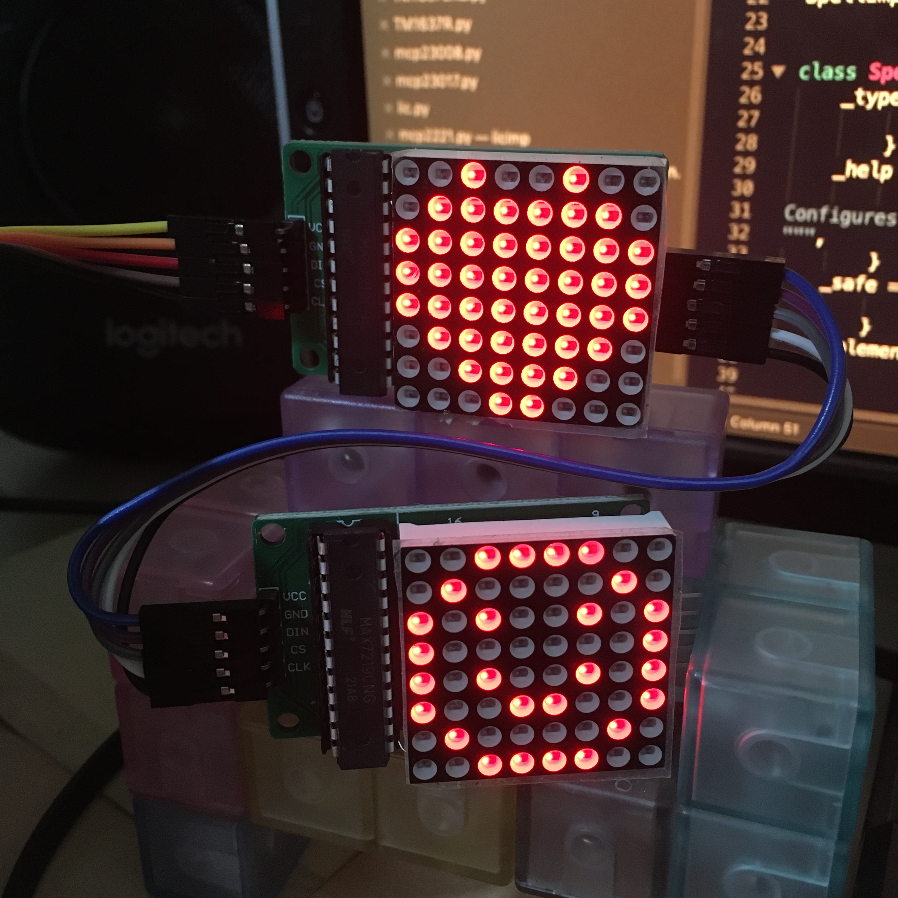
The TM1637 controller that's used in that LCD was a bit awkward to work with, but I was getting the hang of driving these devices. I came across a fancy 8x8 LED matrix display which looked like it could be fun, and it was intentionally chainable, so you could put two or more together to make a larger display if you wanted. The MAX7219 chip that controls these displays isn't a matrix display. It's actually a 7-segment (plus decimal dot) display which can drive up to 8 digits. It just happens in this example to have been wired up to a square matrix, which makes it kinda cute. The way to talk to it by clocking the commands and data into the chip was a lot easier than the TM1637 as well.
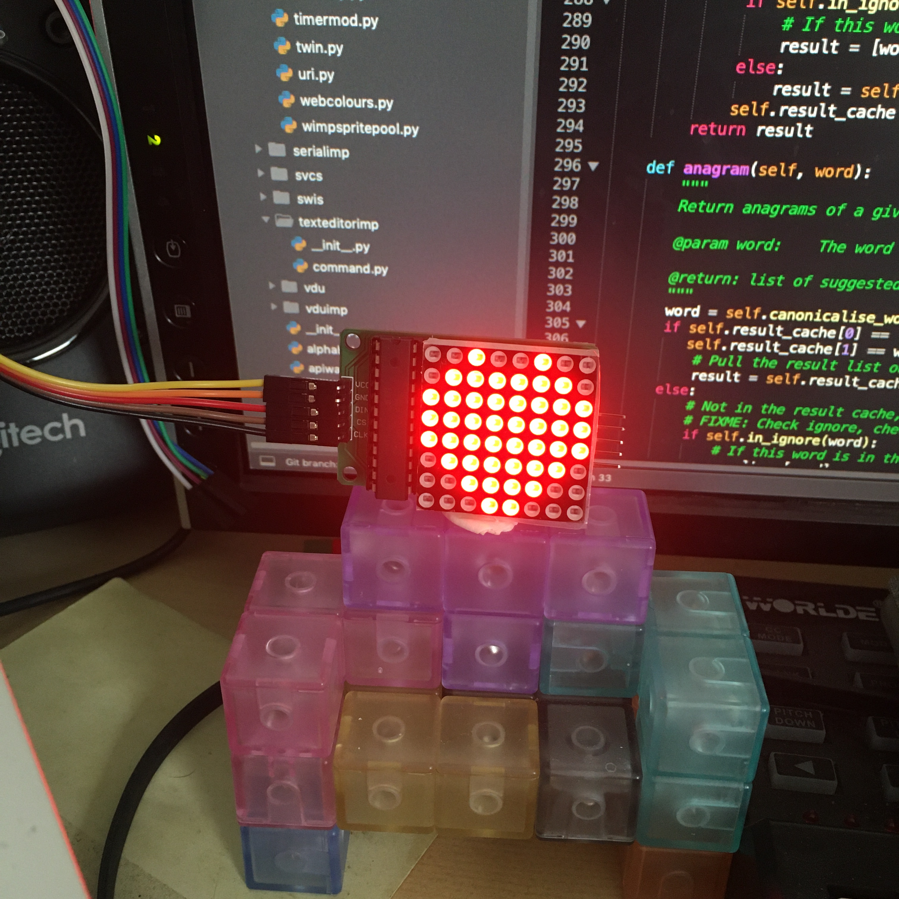
As I mentioned, these can be changed together as well, so you can use more displays with the same data lines.
Frame device abstraction
The graphics system in RISC OS Pyromaniac is set up so that there can be multiple implementations, each of which does things differently. The base 'null' implementation does nothing with graphics operations, and that's the default - most of the time we do not need any sort of graphics system to test things. Based on this implementation is the 'cairo' implementation, which provides most of the rendering functions that you might expect. Almost all the other graphics implementations are derived from this.
However, directly deriving from the 'cairo' implementation was sometimes a bit involved. The GTK, WxWidgets and VNC implementations have similar code that handles the regular redrawing of the Cairo surface to the user interface. I wanted to make this easier, so I created a simplified implementation called a 'FrameDevice'. The FrameDevice is focused on having a bitmap which regularly updates for the user. It intentionally doesn't need to worry about most of the things that the full graphics implementation handles, focusing on transferring the frame buffer to the thing that displays it.
The FrameDevice idea came about because of the OLED display that I created as a graphics implementation. The OLED display - an SSD1306 - was a 128x64 pixel display that could be controlled over I²C. Having a simple interface to the I²C devices, and with the system for writing to the SSD1306 being so simple, it wasn't all that hard to get something that worked. It wasn't very fast, though, as the initial implementation transferred the entire display every time anything changed. With a little bit of caching and checks for changed rows, the device can be made to be quite responsive.
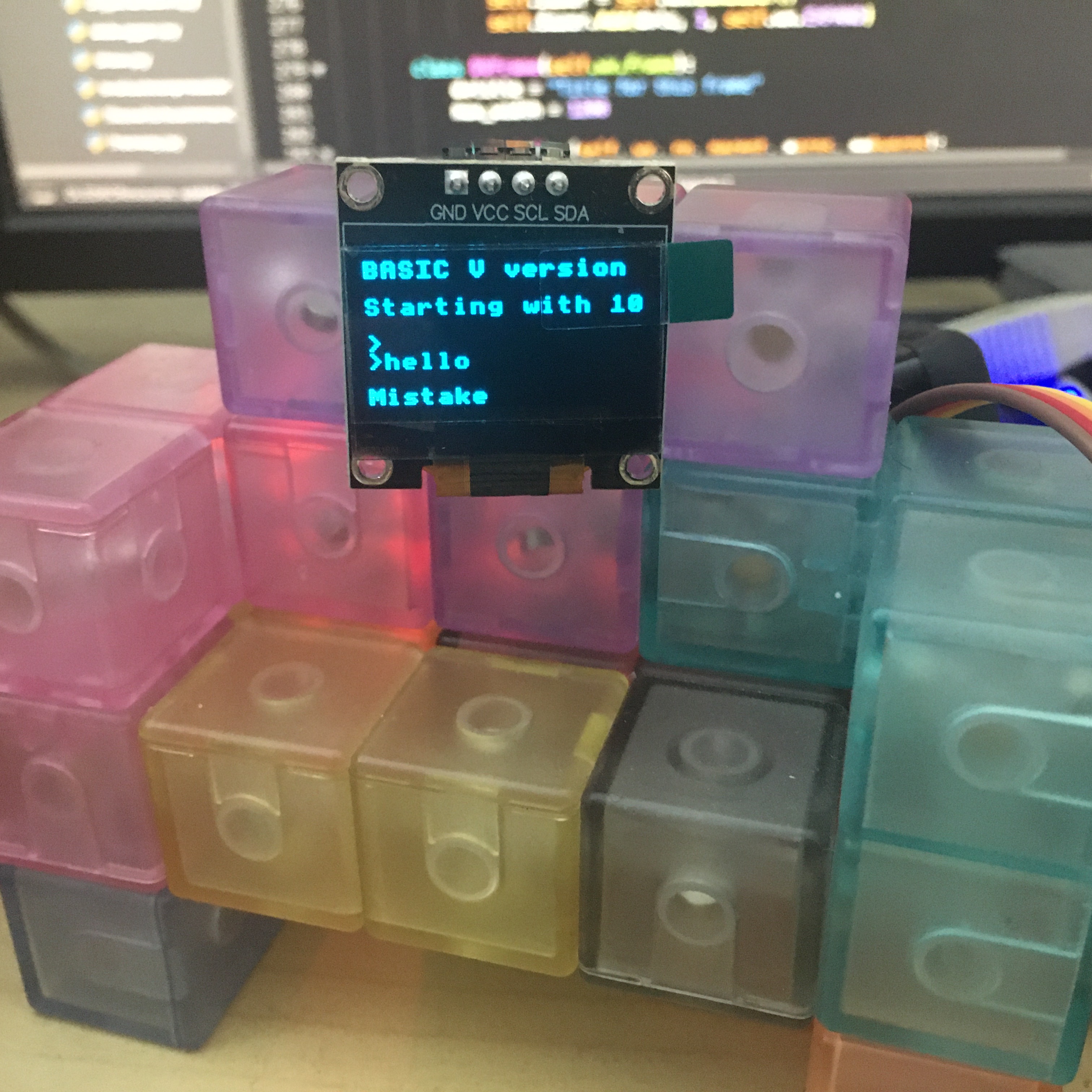
It works pretty well and when used interactively it's not at all bad. Once the speed had improved, it was possible to enable the flashing cursor, which made the display feel a lot more like a real device.
Of course, proper animation makes the display look a lot more like something that might be useful. I'm not sure what it might be useful for, but it's still a useful device. The shimmer you can see is largely from the difference between my camera and the refresh rate of the display.
The OLED display can also be used vertically. I wasn't really sure this would be useful, but a friend suggested that actually this would work really well for Tetris. I'm not going to write a BASIC Tetris, but it could be fun to try out.
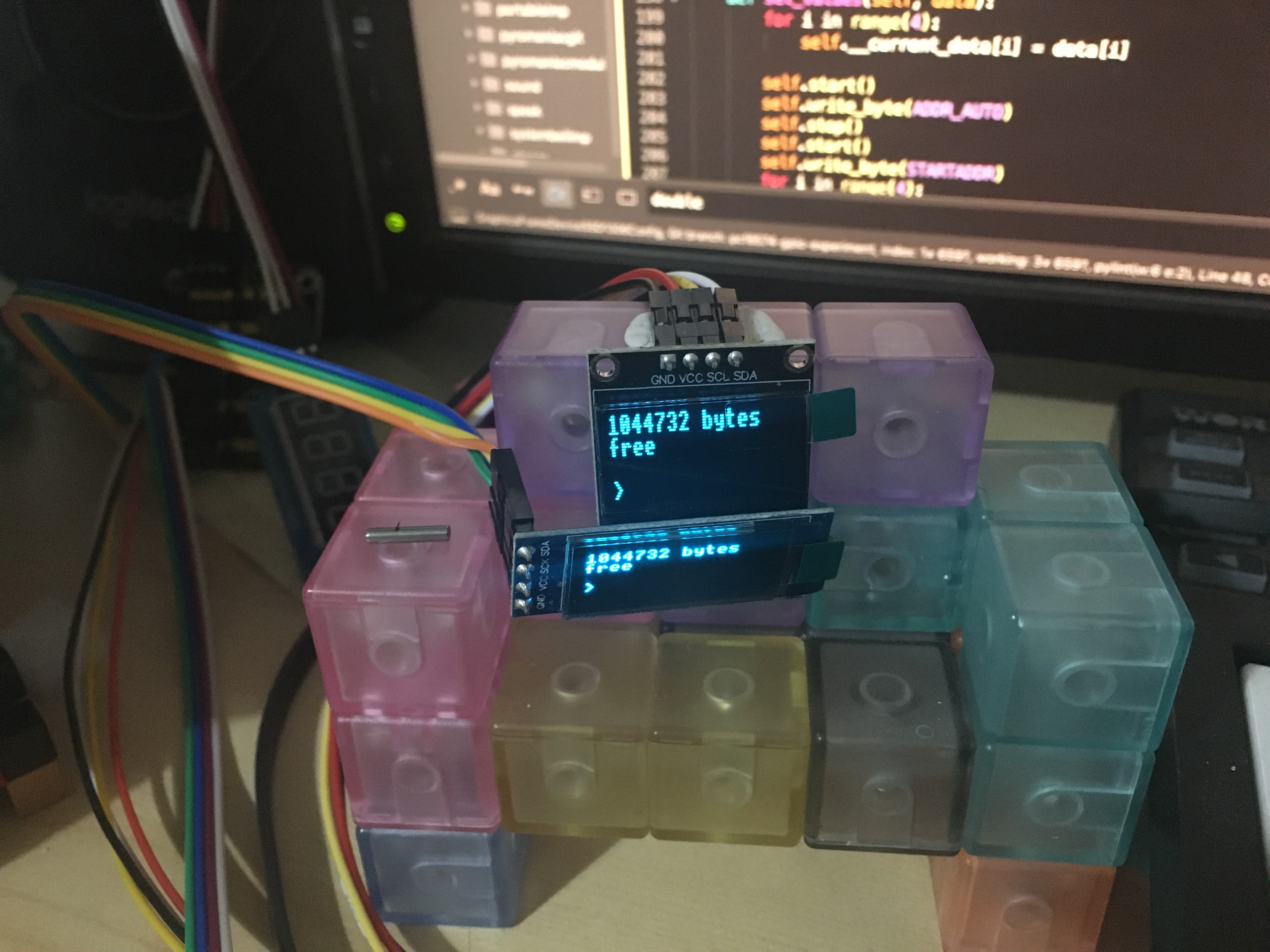
I had two of these displays, with different dimensions, and at one point I accidentally left both of them plugged into the I²C interface at the same time. Basically, having two devices on the bus which are both trying to respond to the same address should not work - their responses should interfere with one another and cause the protocol to break down because they won't be timed right. The devices have the same controller, so it is likely that they have the same tolerances for the responses they give over the I²C bus. So what ended up happening was that both devices displayed what I was sending. I'm pretty sure this was not an intended use of this device, but it was amusing to see!
About a decade ago I got a USB LED display - the 'Dream Cheeky LED message board' which has some example code to drive it. It's not a complex device and has such a simple protocol to set the LEDs that it can certainly be made to work with the FrameDevice interfaces that I had just created. The device is interesting in both its size and how it works.
Firstly, it's 21 x 7 pixels, which means that we're going to be able to display text but will lose the bottom row of the usual 8x8 characters. Secondly, the display isn't persistent whilst it's powered. If the device does not receive information within about 0.4 seconds it will clear to black. That's actually not too terrible, as we can give a minimum refresh rate of 0.3 seconds and be sure that it's updated often enough.
Just because it's possible to display RISC OS on a 21 x 7 display, doesn't mean that it's a good idea to do so. It works, but it looks pretty awful.
It's not actually necessary to have physical hardware to use these FrameDevice implementations. Two implementations that were created show the frame buffer using the console. Instead of outputting the frames to a device, we just write the pixels as solid characters in the console. The console implementation is the most rudimentary. It issues a 'home' at the start of the frame, and then writes out the frame buffer with a space for a black pixel and * for a white pixel. If you scale the font down, you get a reasonable graphics display. The ansi implementation is slightly more advanced. Instead of writing out the solid pixels as an asterisk, it uses the Unicode character for a full solid block. And it changes colour to one of the primary or secondary colours based on the colour requested. This means that you can get rudimentary graphics out of a text terminal.
As I mentioned in the earlier section, the graphics system gained the ability to change the border colour. The main reason that this was added was so that the Turing screen could use the border colour configuration as a way to control the rear lighting on the module. Wiring through the border colour wasn't that hard. Although it is something of a special case for the palette operations, we already have some special cases for the pointer colour selection. FrameDevice can take these colours and pass them to the device if they wish to use them.
An interface library for the Turing Smart Screen had been created in Python, which was very cool. However, it required the GPL, and I try to avoid requiring GPL-based open source where possible. So I wrote my own version from scratch, and made it open source.
ADC operations
Although I had made the I²C and GPIO work on the MCP2221 interface, there were a couple of other features of the device which I had not added support for. There were ADC and DAC functions which could be used in place of the GPIO pins. They aren't that hard to work with but of course, RISC OS doesn't have a good system for analogue operations, either input or output (except for sound, which is quite different). For analogue input, the BBC ADVAL interface is the best that we have, which is a limited interface that goes through OS_Byte &80 (and others). It was used on the Acorn I/O Podule and Morley Analogue/User port expansion Podule, which provided a user port (which is like GPIO and strictly could be emulated by the GPIO module) and a joystick port.
The interface isn't too terrible for its age actually. It had a variable number of bits per conversion and can support up to 4 ports. However, I wanted to be able to do it properly, with a real registration interface and SWIs like we're used to for accessing the analogue data. So I created a new ADC module that could allow the reading of the analogue device in several different ways, and supported multiple devices, with different update rates, data ranges and accuracies. It is hardcoded to use the first device (the only device) as the ADVAL source, so you can access the inputs just like you would on the BBC.
The module is not well enough defined yet, and it sits on an experimental branch, but I've created a few implementations so that it can be used to access different devices. The MCP2221 was the first implementation and it works pretty well. I got a little thumbstick to play with and wired it up to the ADC so that I could read what it was doing.
A tiny little BASIC program to show the analogue values using ADVAL shows that it's working - it might not be especially impressive, but it does the job. I think we'll just gloss over the fact that I'm using a MacBook Pro to emulate RISC OS and talk to a USB device, just to do the same sort of thing that a BBC could do over 40 years ago.
I wasn't content to have something that I could play with manually. It had to be tested, so there are tests to make sure that the module works properly and that the implementation returns correctly if it gets the right results from the controller. And I didn't stop with just the MCP2221. If you're using RISC OS Pyromaniac for testing an analogue device, you would want to be able to have analogue input that was suitable for your tests. One of the implementations I created was the pattern implementation, which allows you to request analogue input that follows a defined pattern, rather than just returning fixed values.
The idea is kinda neat, I think. You configure the type of pattern you want to use and the parameters, and then you run your test and the ADC returns those values in the pattern. You could have it moving just as you would in a game, or a varying sine wave like you might get for temperature or a set of random peaks for impacts. You could do lots of things with it. However, I've only implemented a circle. Channel 1 and 2 follow a sine wave, with one of the channels offset from the other, so they effectively follow a circle. Not very exciting, but it does the job.
The PCF8591 is an I²C device that provides an analogue conversion on up to 4 channels. In that respect, it's similar to the capabilities of the BBC, although it's I²C so it's not especially fast. For some things, that doesn't matter, though. I created an implementation that used this device as well. It's sufficiently simple that the implementation could be rattled off in a few hours. The chip can actually be used in different configurations with the ports being used relative to 0V, or relative to one another. That's a useful feature, which the module at the moment doesn't allow you to configure. It would be really nice to be able to read the configurations that were available and be able to set the device up in different ways. However, that will come later.
There is some simple example BASIC code for reading the PCF8591 on the riscos-examples repository, which also includes a couple of notes about how the board I was using had some hard wired devices which were useful for experimentation.
I wanted to create a more visual representation of the inputs, so I wrote a slightly longer BASIC program which could display the channels as two pairs of related axes - basically so that I could see how my thumbstick was working. It's pretty neat that it's working. The next step would be to have a little BASIC program that showed a scrolling graph of the input values, but I didn't get around to that.
As the PCF8591 didn't take much time at all, I created an implementation for another analogue device that I'd picked up from AliExpress. It's actually a small microcontroller which has integrated ADCs and a serial interface - it outputs the values from the ADCs to the serial port about once every half second. It has 10 ports, so you're getting 10 readings at 2Hz, which isn't especially useful as a joystick, but would be just fine if you were measuring the moisture content of your greenhouse or current wind speed. The implementation is a little more involved for this device because we have to run a background thread that pulls the values from the serial port, and can then feed the most recent results to us when requested. Not hard, really, but just more involved. It looks like the module was all ready to be published to GitHub, but I've not got around to tidying it up yet.
The other ADC device that I created an implementation for was the ADS1115, another I²C device, but one which has a lot of different configurations and has 15-bit accuracy. There's some example code to access it on the riscos-examples repository. There's not a lot to say about that - it works, and it had a similar performance to the PCF8591.
All the ADC work is still too experimental to get merged. Whilst it's one of the most tested, it's not documented and the design isn't really flexible enough for use on RISC OS Classic. It only really works well on RISC OS Pyromaniac because it uses the implementation system to provide the different devices, and that's not all that useful for the real world.
PWM operations
One other common operation for driving physical hardware is Pulse Width Modulation (PWM). This is a means by which output can be turned on and off very fast to give slower or dimmer devices. It's commonly used for LED and some motors but could be used for other things as well. As it is such a common operation, I wanted to create a direct interface that you could use, like the ADC system, to drive multiple dynamically registered devices.
However, the first thing to do when trying this out is to buy some random hardware and see how it works, because clearly that's a good plan and never ends up with drawers full of hardware that you've never got working. The first bit of hardware that I got working this way was the FanHAT, which is a fan for the Raspberry Pi which is driven over I²C and also has a tiny OLED display. The fan is controlled by a PCA9685, and the OLED display is the SSD1306, for which I had already written the display implementation.
Writing some small BASIC code to control the fan was pretty easy. The intention was to take this code and use it to create a FanDriver module that plugged into my FanController stack, but I never got around to doing that.
If you listen really hard, you might just about be able to hear that the fan changes in tone as I change its speed. It's rather quiet on the video - but that is a good thing as you don't want to be able to hear the fan normally. Anyhow, having a simple program to control the PWM on that device was pretty neat, so I started implementing a PWMDriverPCA9685 module to be able to control it. It's got a relatively simple interface, but one which is hopefully generic enough that I can work it into a controller module that can manage multiple devices in the future.
The idea is that I would create a PWMController module which a PCA9685 module would register with and offer its services. The interface could come directly from what I'd learnt about the different types of PWM controllers. Each device will have slightly different capabilities and features, so finding a common enough set to be generally useful is fun. However, I've not got there yet and the module is specific to the PCA9685.
Interestingly, I chose to do it through separate modules rather than through implementations when I created these interfaces. I don't think there was much more thought than that the implementations tied it to a single device and that was frustrating for my IIC and GPIO modules, so I probably wanted to be more RISCOS-y about it.
The second PWM driver that I created was because Dave Thomas mentioned that he'd used it and that it was really bright. So I bought one - and found that it was really bright. The PiGlow is another Raspberry Pi focused device that has a spiral of coloured LEDs on its face - 18 of them, which are independently controllable as PWM devices. Whilst the FanHAT had only 1 of its PWM controls able to do anything, the PiGlow had all 18 controllable and able to be seen.
As before, I created a small BASIC program which controls the lights and used a little sine function to make them fade in and out.
The image you see there is quite bright - it's not just the camera picking the lights up really well - and it's only using a small fraction of the range that the device can show. The PWM has a range of 0 to 255 for off and fully on. The fading code demonstrated only uses values 1 to 13 for the fade effect. It really can be very bright!
Having got the PWM working, I created a new module for this SN3218 PWM controller, based on the code that I'd used for the PCA9685. The module works and it's relatively useful, but I need to refactor it into a controller, make a registration interface and allow for some more generic controls. That can all come later. All this work is on experimental branches and it needs a proper interface document writing too.
RTCs
The Real Time Clock (RTC) is probably the main reason that I²C is present in the RiscPC and thus that the IIC module is available. Strictly it's not just the RTC, but also the non-volatile RAM, that is provided through the PCF8583 chip. The PCF8583 provides 240 bytes of battery-backed memory and a clock that counts in centiseconds. It also has an alarm and trigger pin, but that was never used on the RiscPC.
Early in Pyromaniac's development (around June 2019), the IIC module was created, with some simple registration to allow the PCF8583 to be accessed. At that time I intended to make it possible to add new registrations of other devices. However, I didn't get around to doing anything further with it until 2022. All the internal IIC interfaces (with PCF8583) were moved to a separate implementation so that they could be used as the default implementation. This would also allow other implementations to be added if needed.
However, if I wanted to get things working properly, I needed the RISC OS system to use the PCF8583. On RISC OS, the RTC is managed through the RTCV vector, which is claimed by whichever module supports the hardware running on the system. The RTCHW module on the RiscPC uses the PCF8583, and so once it is present, the clock is then handled by the hardware.
I had to re-write the RTC handling in RISC OS Pyromaniac to call the RTCV interface so that we use the RTCHW module, but that wasn't too hard. The code actually calls the vector and if the vector wasn't claimed it falls back to the standard system time code that it had originally used. This means that even if there isn't a module to provide the time, we still get time moving. Most of the time we aren't caring about how the time gets there when we're testing - just that it works. As part of the changes, though, it is now possible to write to the RTC, and even when we're using the host clock directly, this is tracked as a delta from the real time so that the emulated system still works as expected.
Finally, I wrote an implementation of the RTCHW as a PyModule which uses the PCF8583. This can use whichever PCF8583 is connected to the IIC module - whether it's a hardware implementation or the emulated one that actually talks to the system clock anyhow. So many different ways of getting to the system clock, but it's all intended to allow the system to be close to RISC OS Classic, or to just be a general RISC OS which uses different interfaces.
By this time, I'd also obtained some other RTC devices - the DS1307, DS3231 and a PCF8563. They're very similar in function, but they don't all provide the NVRAM data. Most RTCs don't have centisecond accuracy, so that also makes them different. The DS3231 also has a temperature sensor on it, which isn't used by the driver, but it could be exposed in the future when I finally get around to implementing the Sensors module.
Temperature sensors
I bought a few temperature sensors to play with. Largely I²C devices, because they're pretty simple to work with. There's some simple AHT10 temperature sensor reading code up on the riscos-examples repository. It's not an especially exciting chip, but reading it works just fine and its values seem plausible. I also had a play with an LM75 chip, which is relatively common in older PCs as a temperature monitoring device.
My intention, in the future, is to create a Sensors module which will be able to dispatch for different types of sensing devices, not just temperature sensors. I made a start on it a couple of years ago when I was looking at the FanController work, but I've not returned to it - just too many other interesting things to do. Plus nobody's particularly rushed to get information from external sensors.
Serial
I wanted to provide a simple implementation of the OS_SerialOp interface so that we could at least test programs that used the serial operations. Initially, this was just a simple pair of implementations in the SWI handler, one of which allowed you to use the serial port for accessing a file, and another of which was a null implementation that did nothing.
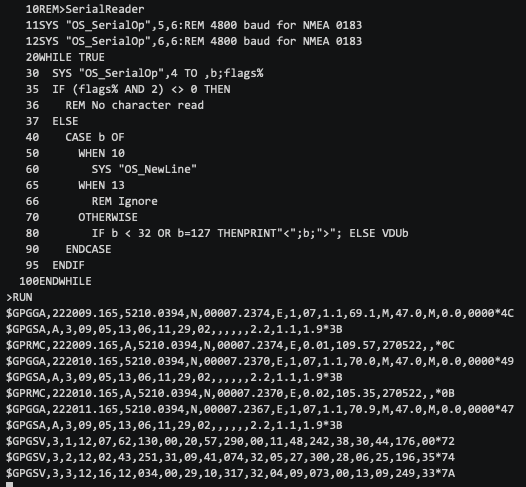
As I wanted to access real devices, I created a new implementation that used the Python 'PySerial' package. This allows access to host serial ports, and also through a network protocol that lets you serve a host's serial port over the network using the RFC2217 protocol. The main serial device I had was an old GPS device, which talked NMEA 0183 to report your GPS position over serial. However, the USB serial interface it used wasn't supported on my macOS machine. It was supported on my work Linux machine, though. I could use the network protocol to proxy the serial port from the Linux machine to my MacBook and still test things usefully (plus of course I could use it directly on the work machine).
The result is that, given a little time for it to establish a lock, I can get useful satellite positioning out of it using the serial port. There's a little video of it running, and showing my position as a NMEA 0183 sentences.
Additional implementations
Although I started with the MCP2221 for I²C and GPIO, other devices provide these functions as well. Most obviously, the Raspberry Pi has I²C and GPIO built-in and they are accessible through the header pins. The pigpio Python package is one way to have access to the I²C and GPIO pins. I had dug out my old Raspberry Pi, which had been sitting in a box for about five years, set up a modern Linux on it and installed the necessary components to use pigpio and Pyromaniac. Surprisingly the pigpio package is pretty easy to use and it wasn't too hard to write an implementation for the I²C operations. I had been a little concerned that Pyromaniac might not run on the Pi, but once Unicorn was installed, it worked as just fine. So that's pretty good to know!
The pigpio package also supports remote access, which is useful. I can run the pigpio server on the Pi, and then connect to it from another system. That means that I can just leave the Pi in another room and poke at it remotely, without even running Pyromaniac on the Pi itself. It might not be a commonly used feature, but it's handy to have another device on hand - and it means I can test out things that work in the same way that they would on the Pi.
The CP2112 is a USB-to-IIC/GPIO interface, similar to the MCP2221. Unlike the MCP2221, however, I wrote the entire implementation from scratch, without using any open source packages to interface with it. Partly this was due to greater confidence in writing such implementations, but also I knew that working with a bad package was likely to be more limiting after my experience with the MCP2221. The datasheets weren't too bad, although they did split some of the functional descriptions across two distinct documents which led to much flitting back and forth.
The other I²C device that I got working was the CH341 USB bridge chip. The CH341 is an interesting chip because it can do a lot of things. It has functions for IIC, GPIO, parallel port, serial, and SPI. It shares outputs for some of these, so it's not possible to use all the interfaces at once, but it is quite a versatile system. It is implemented as a queued command processor - you give it the things that you want it to do and it goes and does them. So you might give it all the commands necessary to perform an I²C transaction and then wait for it to give you the result.
Whilst it is very clever, it is not well documented - at least not in English. There is some documentation and example code, but it doesn't really fill in the gaps of how it all fits together. It does feel like whoever put it together had the awesome idea of making it as flexible as possible so that it could be used for many purposes. But then they never got around to telling anyone how to use it well - or maybe just not in English. There are a few devices on sale which use the chip that are just programmers for embedded systems, and whilst there is support in Linux and BSD, the comments in the code show that it was written to work with the real chips, rather than to match the documentation.
However, I have I²C and some of the GPIO working, so that's pretty good.
When I was trying to find a device that did input over I²C I came across a little keypad on AliExpress. I thought it would be quite nice and easy to be able to query the interface through the IIC module and get back an indication of which button was pressed. That wasn't what the device was. It turned out to be an MCP23008 - a GPIO extender over I²C, which was wired through 8 lines to the keypad. To read the keypad you make 4 of the lines outputs, and 4 of the lines inputs, and then you put a signal down each and see which line responds - that gives you the position of the pressed key. It's not hard to do, but you have to be able to communicate with it to set the GPIO pins, over I²C.
I wrote some simple code to do this in Python and it all worked fine, so I ported it to BASIC and published it on GitHub as I hadn't found any examples of driving this device through Google and GitHub.

However, the MCP23008 is a pretty useful chip to be able to use as it gives 8 extra GPIO ports that you can drive. So I created a GPIO implementation for this chip. This means that when you communicate with the GPIO using that implementation it actually goes to the IIC module to be processed by the device, and gets a response back. It isn't going to be as fast, but sometimes you don't need fast for the responses on those pins. In Pyromaniac, talking to the device might go from the GPIO module, to the MCP2221 driver, to the IIC module, to the USB device, and finally reach the I²C device. I think this is pretty exciting, but it shouldn't be surprising as it is exactly how a modular system should work.
Like the MCP23008, the MCP23017 is an I²C GPIO expander, although it provides 16 ports, rather than the 8 provided by the MCP23008. And the PCF8574 provides an 8 port GPIO over I²C as well, and its friend the PCF8575 provides 16 ports. There are implementations for those devices as well.
The work on the I²C pigpio implementation also gave access to the GPIO ports (as the name might suggest), so it's possible to drive the Pi pins remotely. The first test for that was using the Blinkt LEDs with similar code as I had used previously, but targeting the GPIO on the Pi over the network, and it worked very well - not noticeably slower than accessing the pins directly.
For the Raspberry Pi there is also an RPi.GPIO package, which only supports access to the GPIO. This might be more useful to some people, so I created an implementation for that as well.
Two final implementations were created for GPIO - the 'static' implementation, and the 'wxwidgets' implementation. The 'static' implementation just lets you define how many pins you want and the constant values they should have. The 'wxwidgets' implementation however lets you see the state of the pins in the UI, and even change them if they were made to be inputs.
Internal IIC implementations
The RTCHW and many of my BASIC programs were tested against real hardware to make sure that they worked, and then tests were written to make sure that they didn't regress, even if the hardware wasn't there. The tests were created by implementing stub versions of the devices as internal IIC registrations. These registrations became a bit fiddly, as we didn't always want the same I²C devices present and in some cases, the devices used the same address to talk to them. So instead of just having plain registrations, it's possible to configure which devices are enabled, and the addresses that they'll be made available at.
In the configuration, you can specify the names of the devices that you want to make available through the internal driver, and the address they should respond to. This means that even if the devices have addresses that would clash, they can be reconfigured. For example, to enable the PCF8583 and the SN3218 at a different address, you might use the configuration pcf8583;sn3218=32.
There are a few I²C internal implementations made available at the moment:
aht10- AHT10 temperature/humidity sensords1307- DS1307 RTC/CMOSds3231- DS3231 RTClm75- LM75 temperature sensormax30205- MAX30205 temperature sensormcp4725- MCP4725 DACmcp9808- MCP9808 temperature sensorpca9685- PCA9685 PWM driverpcf8563- PCF8563 RTCpcf8583- PCF8583 RTC/CMOS storagesn3218- SN3218 PWM driver
Where next...
Resources
-
Part 1: Introduction
An introduction to Pyromaniac. -
Part 2: Changes by month
Summary of the changes broken down by month. -
Part 3: Details (1)
In depth discussion about some quick hacks, Jan Vibe's graphical ditties, Git and others. -
Part 4: Details (2)
In depth discussion about the user interface changes and testing. -
Part 5: Details (3)
In depth discussion about the hardware interfaces. -
Part 6: Conclusion
Some final words about the year. -
Appendix: Summary of the changes
A quick summary of the changes in 2022. -
Main Pyromaniac Site
Main pyromaniac site with resources, examples and other links.